 |
|
|
|
Simulation of Sidescan Transducer
Arrays
|
Page: 1, 2, 3
Simulation af a
damaged
and a bad Sidescan Sonar Transducer
|
|
|
Now we can also have
a look at how the beampattern is altered in a transducer with one dead
piezoceramic element or where the elements are mounted with a too large
space in between.
The
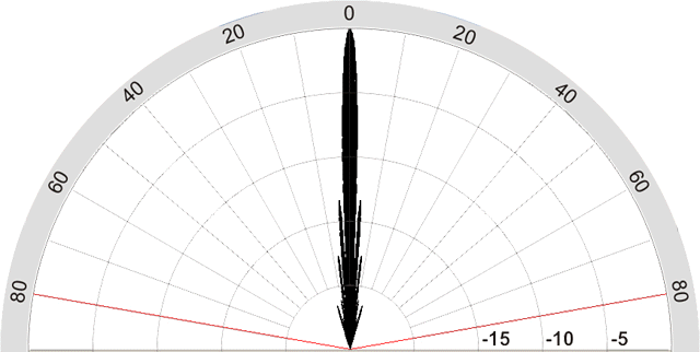
first figure again is our perfect sidescan sonar transducer we already
saw on page 1 and its beampattern at 50kHz. The array is 610mm long,
consisting of 6 inividual piezo-elements measuring 100mm x 25mm at
the side facing the water, the elements are spaced at 2mm.
|
|
 |
| Figure
1a:
Sidescan Sonar Transducer Array, 610mm x 25mm |
|
|
 |
Figure 1b:
polar plot for the calculated horizontal energy distribution
of the sidescan transducer in Fig.1a working at 50kHz.
89% of the
emitted energy is concentrated in the central lobe.
|
|
|
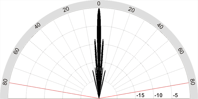
What
happens to the beampattern if one transducer element is broken as in
Fig.4a, for instance by a broken electrical connection or because it
loosened from the backing bar?
|
 |
| Figure
4a: Sidescan Sonar Transducer with a broken element |
|
|
 |
Figure 4b:
polar plot for the sidescan transducer from Fig.4a
|
|
|
As
can be seen in the polar plot, the main change, as to be expected, is
in stronger sidelobes. With our original transducer concentrating 89%
of the emitted energy in the central lobe, this drops to 78% for the
transducer with one missing element.
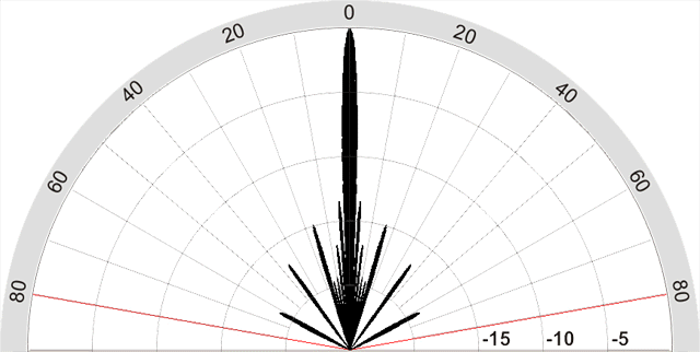
When building a sidescan sonar transducer, one should not space the
individual elements more than 1/4 wavelength (statement of Sture
Hultqvist in the Geotech Sidescan Sonar Forum). But what happens if we
space them more than 1/4 wavelength, that is 7.5mm for 50kHz? The next
simulation for our 610mm transducer, this time with the individual
elements spaced 0.5 wavelength from each other, gives an answer: Again
the difference is in the sidelobes, as can be seen in Fig.5b. Because
of the spacing, more energy is lost in the sidelobes, and the
percentage of energy concentrated in the central lobe falls to 77%.
|
 |
Figure
5a: 610mm long Sidescan Sonar Transducer with 15mm (i.e. 1/2 wavelength
for 50kHz) space in between the individual elements
|
|
|
 |
Figure 5b:
polar plot for the sidescan transducer with the elements spaced 0.5
wavelength
|
|
|
|
What we can also see
as a result of these simulations is, that both, the slightly damaged as
well as the "bad" sidescan sonar transducer
with the large spacing of the elements, would both still be
considerably
better than the optimized fishfinder sidescan sonar transducer.
|


